Static Analyses of Bars and Trusses
via the Finite Element Simulation Method with SOLIDWORKS
Application of truss structures in various forms are found all around. Typically, they are featured prominently in the design of cranes, truss booms, telecommunication towers, masts, electric pylons, roofs, bridges, and so on.
From an engineering performance analysis point of view, static analyses of bars and trusses are conducted with the following objectives:
- Determining the internal forces and consequently the stresses that developed in the members.
- Evaluating the axial deformation, the members experienced upon loading.
The following technical points are frequently considered for the computer analysis of trusses:
- The members of a truss are straight and have uniform cross-sections.
- The ends of an individual member of the truss are connected to the ends of other members at joints via frictionless pins. In practical scenarios, such joints may be formed by rivets/bolts/ball and socket joints or via welding to a gusset plate.
- Forces and supports are applied only at the joints of a truss.
Strategies for the analysis of trusses
This section describes the structural details and the modeling strategies for the simulation of truss structures. It also highlights the major features of the truss element within the SOLIDWORKS Simulation library.
Structural details
Irrespective of what form a truss may have, a consistent set of parameters is employed for its analyses. The following technical information are needed before venturing into the analysis:
- The dimensions of the truss:
- The details of the cross-section
- The geometric length of each member
- The orientation angles of the members
- The material properties of the truss members
- The loads applied to specific joints of the truss
- The support provided to the truss to prevent rigid body motion
Modeling strategy
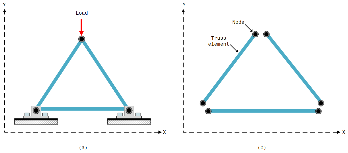
When analyzing truss structures via the finite element simulation method, a basic strategy is to take a structure such as that in Figure 1 (a), split it into its constituent members (Figure 1 (b)), and then treat each member as a truss element. Thus, in the end, a whole structure formed from the assembly of different members is represented by the collective behavior of individual truss elements.
The major steps in the static analysis of trusses are:
- Modeling the skeletal structure (skeletal arrangement) of the truss or a collection of bars within the SOLIDWORKS modeling environment.
- Conversion of the skeletal structure into a weldment profile within the SOLIDWORKS modeling environment, transforming the weldment model into a finite element model (within the SOLIDWORKS Simulation window).
- Running the analysis to obtain the results (within the SOLIDWORKS Simulation window).
PROBLEM 1: Conducting static analysis on a crane
Problem Description
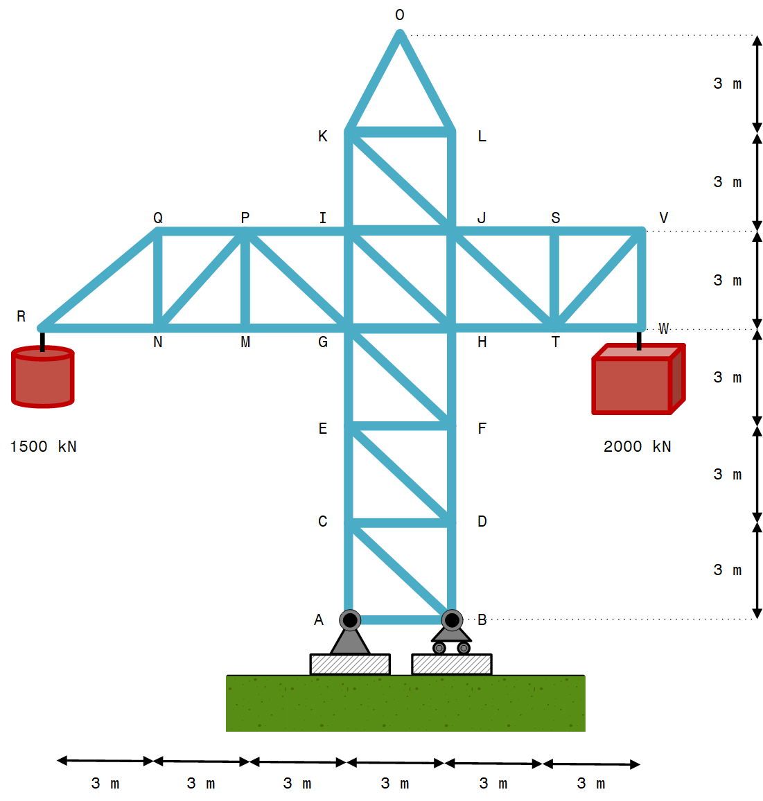
Analyzing the structural performance of a crane used in the spatial positioning of heavy objects on a mega building construction site. A 2D representation of the crane to be analyzed is shown in Figure 2, The crane is subjected to $1500 \ kN$ and $2000 \ kN$ weights at points $R$ and $W$, respectively.
Considering that the members of the crane are derived from tubular alloy steel with its Young’s modulus, $E$, to be $210 \ GPa$. The members have the same cross-sectional detail characterized by external and internal diameters $200 \ mm$ and $80 \ mm$, respectively.
Objectives
Answering the following questions by using SOLIDWORKS simulation:
- What is the maximum resultant deformation of the truss upon the application of the loads?
- What is the distribution of the factor of safety of the members of the crane upon loading?
- What is the internal force/stress that developed in the member $IH$?
Solution
- Part A – Creating the sketch of the geometric model
- Part B – Converting the skeletal model into a structural profile
- Part C – Creating the Simulation study
- Part D – Scrutinizing the results
Part A – Creating the sketch of the geometric model
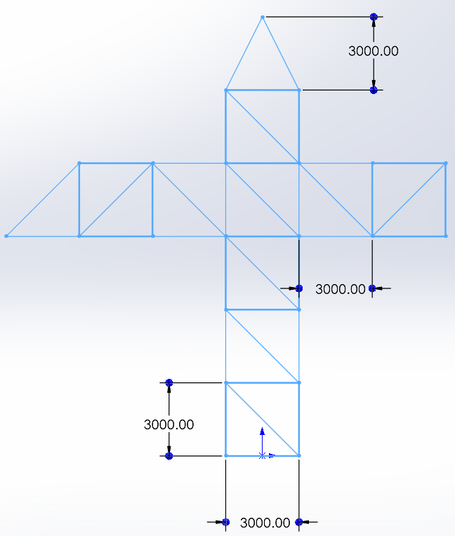
First, a model of the crane structure (skeletal sketch of the model) is created by sketching the lines describing the geometry of the crane with the line sketching tool. The unit of measurement used is the MMGS (millimeter, gram, and second) system of units. The completed sketch looks like the screenshot shown in Figure 3.
This created sketch is just a series of lines with no volume property. As such, it cannot be used for structural analyses. In the next step, the sketched line-based model is converted into a structural model with a volume property.
Part B – Converting the skeletal model into a structural profile
The next step is to convert the line sketches created in the preceding section into a structural model using a special functionality in SOLIDWORKS called the weldments tool, which facilitates the transformation of lines with no volume properties into structural members with volume properties that are suitable for realistic engineering simulation. This is done by prescribing the cross-sectional details for the sketched lines.
To do this, Structural Member command is used from the Weldments toolbar and in the Structural Member PropertyManager window the following options are selected:
- Standard: iso
- Type: pipe
- Size: $33.7 \times 4.0$, – which refers to a tube with an external diameter of $33.7 \ mm$ and a thickness of $4 \ mm$.
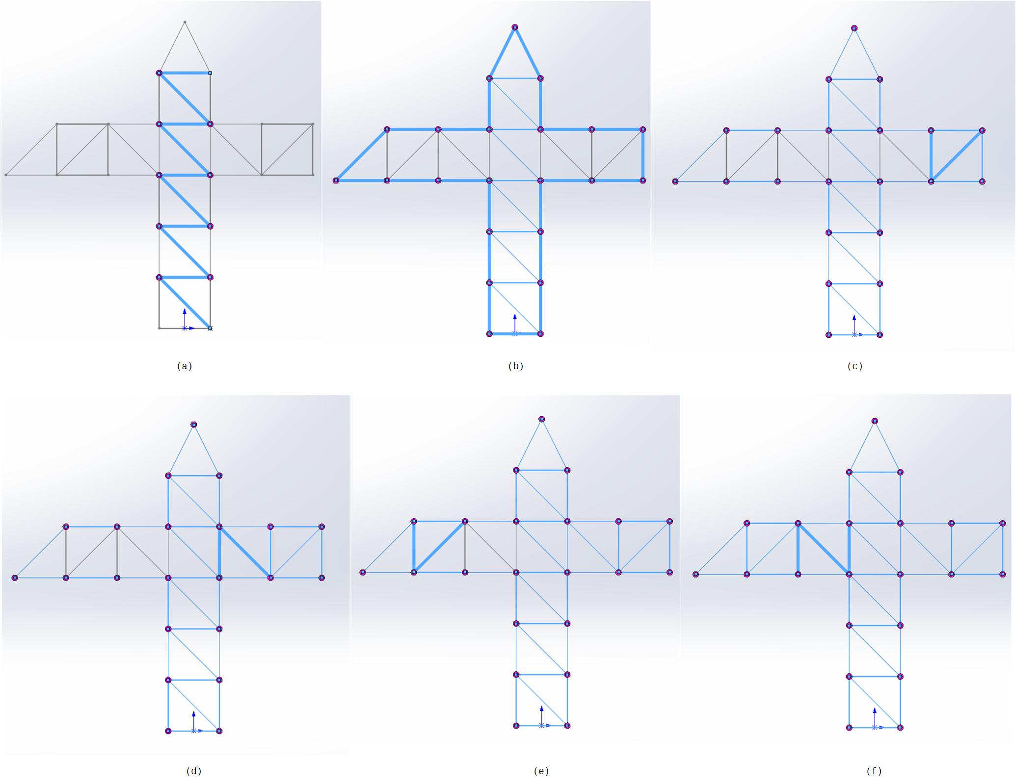
Then, six groups of lines are selected (without applying corner treatment). The series of lines to be selected for each group are illustrated in Figure 4 (a-f).
On completing the above mentioned, the FeatureManager tree will appear with some additional items, like the item Cut list (41) showing that there are a total of $41$ weldment items that make up the crane structure, and the item Pipe, which is the main branch of the collection of extruded bodies representing the $41$ structural parts of the crane.
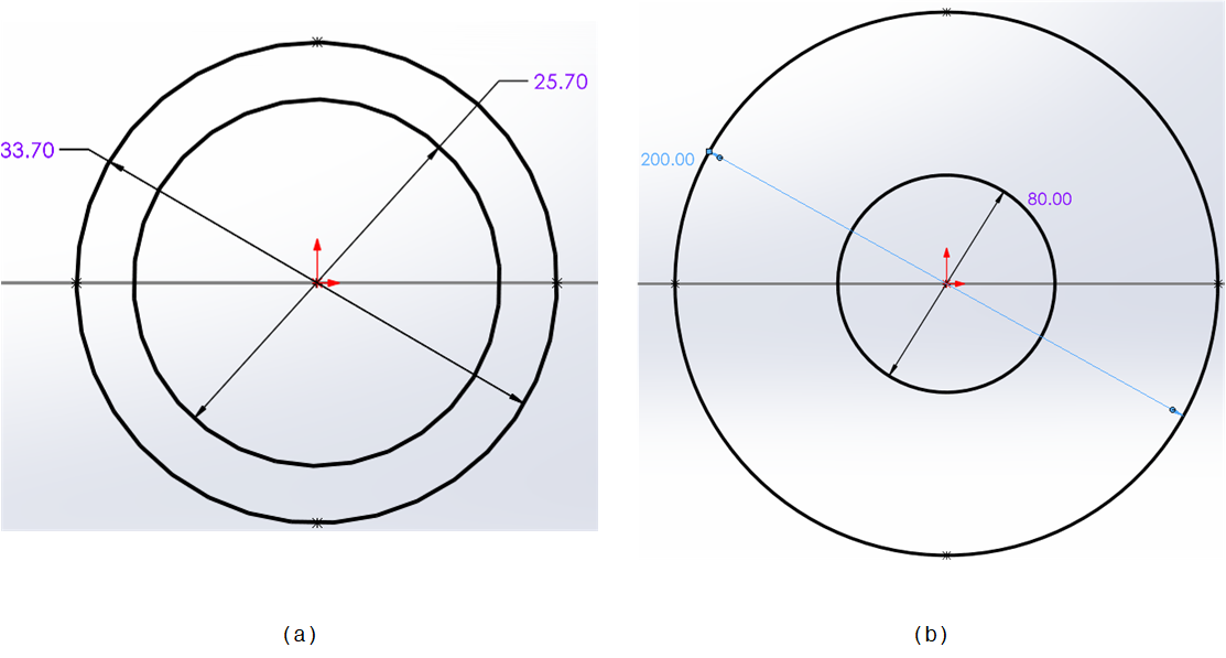
The employed cross-section from the weldment library is not the same as that stated in the problem description. Thus, to change the dimension of this cross-section, the Sketch in the item Pipe in the FeatureManager tree is edited from Figure 5a to the desired dimensions, shown in Figure 5b.
Part C – Creating the Simulation study
In this section, static analysis is performed on the crane structure. For this, after activating the simulation tab and creating a new study, the material for the members is specified, the truss element, fixtures/loads are applied, and finally, the meshing process is initiated.
$\quad$ 1. Activating the Simulation tab and creating a new study
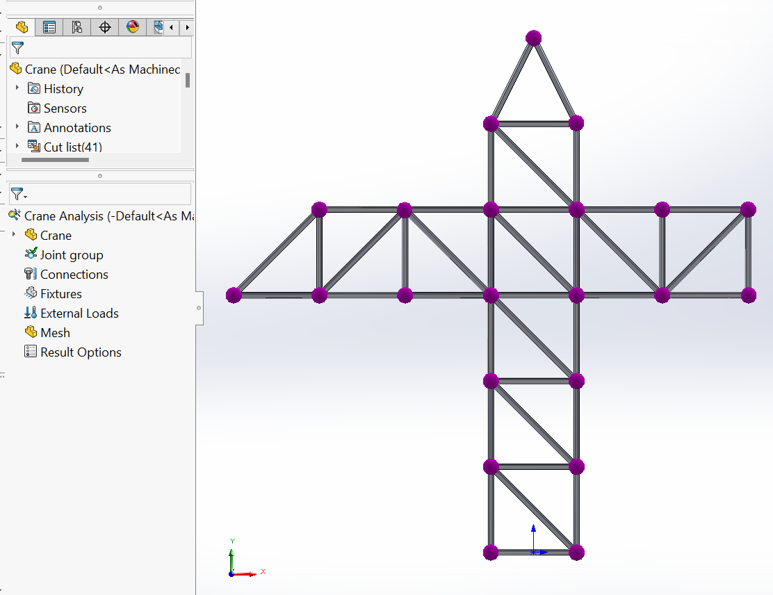
In this step, after activating the ‘Simulation’ tab, a new study is created, named “Crane Analysis”, and the static analysis option is selected in the ‘General Simulation’ properties in the ‘PropertyManager’ panel. As a result, the ‘Simulation’ study tree is launched, joints are imposed at the connection points between the members of the truss, as well as ‘Simulation’ commands become available, as shown in Figure 6.
$\quad$ 2. Adding a material property
It is assumed that each member of the crane is made of the same material. To apply the material to the members, the material database is launched and, in this case, ‘alloy steel’, located in the subfolder ‘Steel’ is selected.
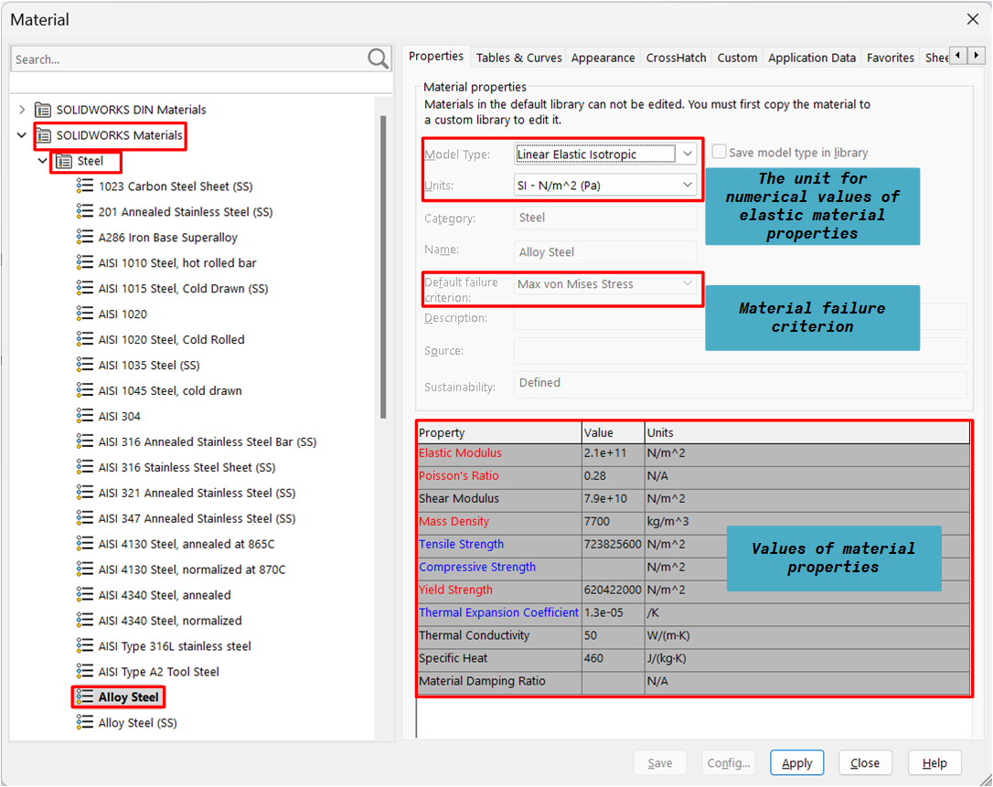
The left side of the ‘Material Dialog Box’, Figure 7, contains a tree of available material types and materials, i.e. material database, which is a multilevel directory. At the top of the tree is SOLIDWORKS Materials main folder, followed by subfolders, each containing materials belonging to the same family. In the properties tab, the names of material properties are either in black, blue, or red font color. In general, the material property names in red are the ones that are necessary for static analyses. A material failure criterion (Max von Mises Stress) and Linear Elastic Isotropic material model are pre-defined for the selected material.
A material is called isotropic if its properties do not vary with direction. Isotropic materials have identical elastic modulus, Poisson’s ratio, coefficient of thermal expansion, thermal conductivity, etc. in all directions.
$\quad$ 3. Changing from a beam element to a truss element
By default, SOLIDWORKS Simulation treats a structural member that is created using the weldment tool as a beam element during the analysis. However, in this case, a truss element is required. The difference is that a beam element resists axial, bending, and torsional loads, while a truss element can resist axial loads only. Therefore, all the structural members, that are under the subfolders in the ‘Cut list’ folder in the ‘FeatureManager Design Tree’ are converted from beams to trusses by editing their definition from beam to truss in the ‘Edit Definition’ option.
$\quad$ 4. Applying a fixture
A fixture is a constraint applied to structures to restrict the movement of its joint/segment when loads are applied. For this analysis, three sets of restraints are applied to the structural model of the crane:
- A fixture that prevents the normal movement to the front view of all the joints (that is the vertices of the crane). This needs to be done because a planar (2D) analysis of the crane is being done in this case. However, in case of a 3D analysis, this is not necessary.
- A fixture that prevents movements in the horizontal and vertical directions at joint $A$ (because joint $A$ has a fixed support).
- A fixture that prevents the movement along the vertical direction at joint $B$ (because this joint is supported by a roller joint).
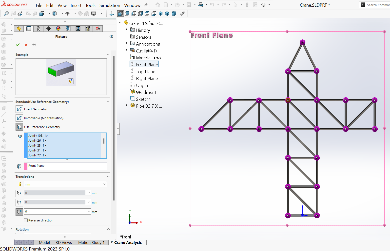
For the first fixture, to restrain the $Z$ motion of all nodes, i.e. to impose a zero translational movement on all the nodes along the $Z$ axis, which will ensure conducting a plane analysis afterwards, in Simulation study tree the Fixtures option is right-clicked and Fixed Geometry is selected. Then, under Fixture PropertyManager and in the Standard section, Use Reference Geometry option is selected to apply restraints. All the joints in the graphic window are selected one by one. Front Plane is chosen from the FeatureManager tree to be the reference plane to apply restraints (noted inside the box regarding the reference plane). Then, under Translations section, the box for Normal to Plane is selected. These options are shown in Figure 8.
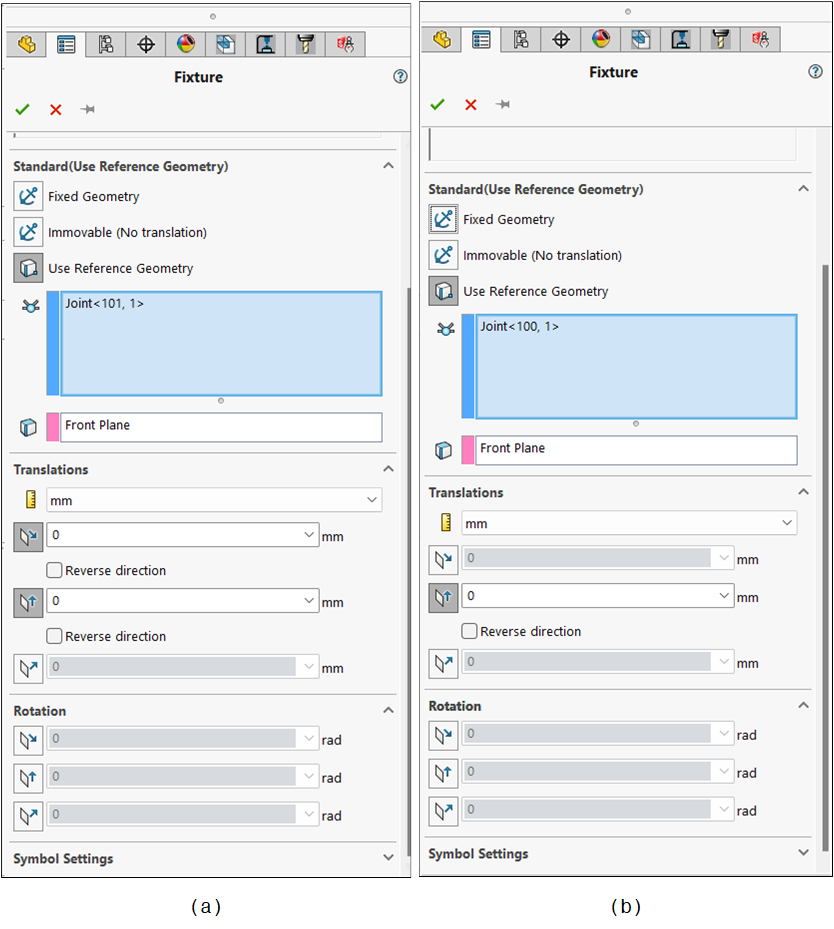
Then, the restraints at joints $A$ and $B$, both located at the base of the crane, are applied, by applying fixture on nodes $A$ and $B$ in steps similar to the ones described in the previous paragraph, following the options shown in Figure 9 (a-b).
For joint $A$, it was also possible to use the fixture named Immovable (No translation); it performs the same function as what was done by using Use Reference Geometry. For joint $B$, the movement was restrained along the vertical direction only, to replicate the behavior of a horizontal roller support.
$\quad$ 5. Applying external loads
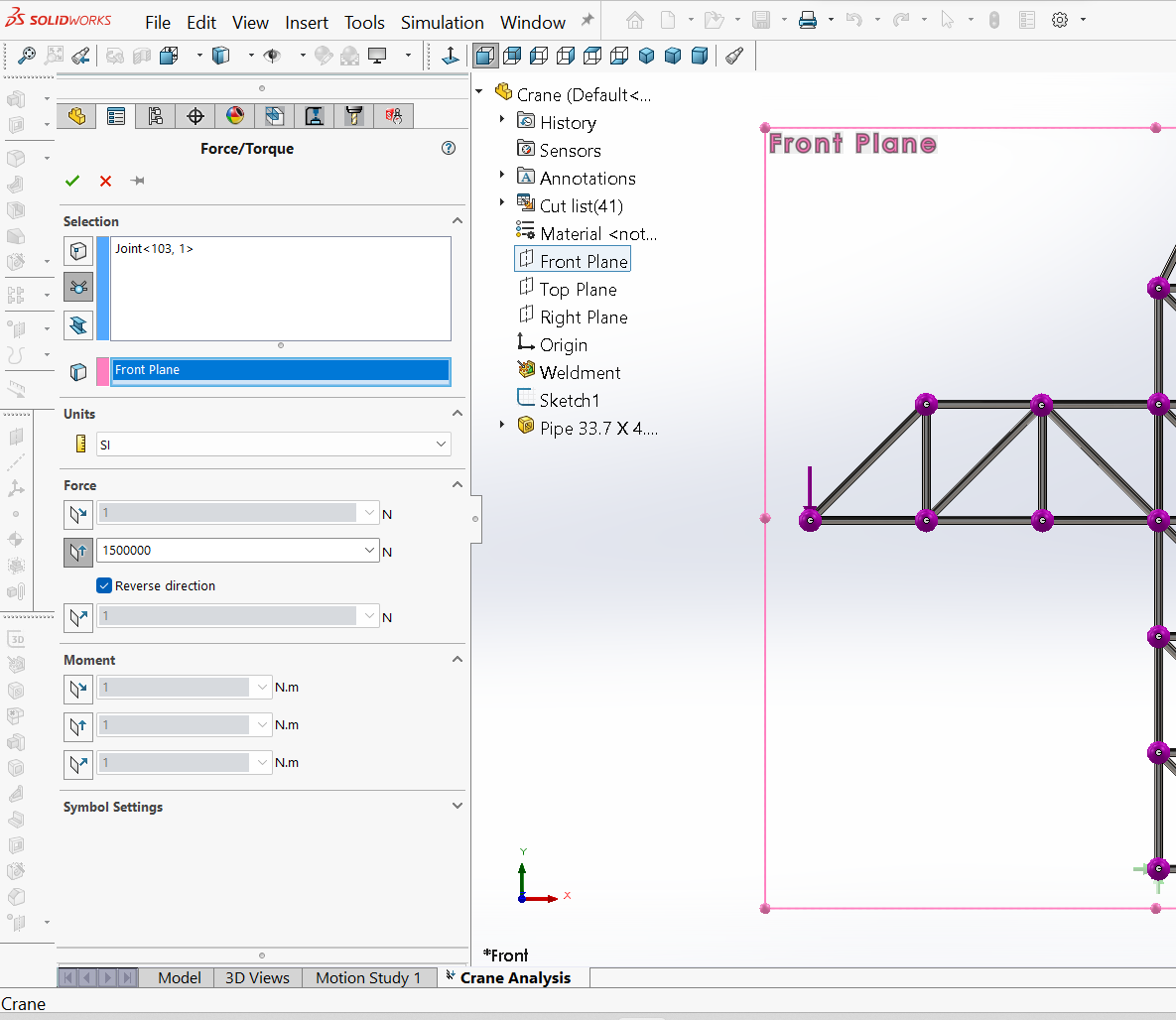
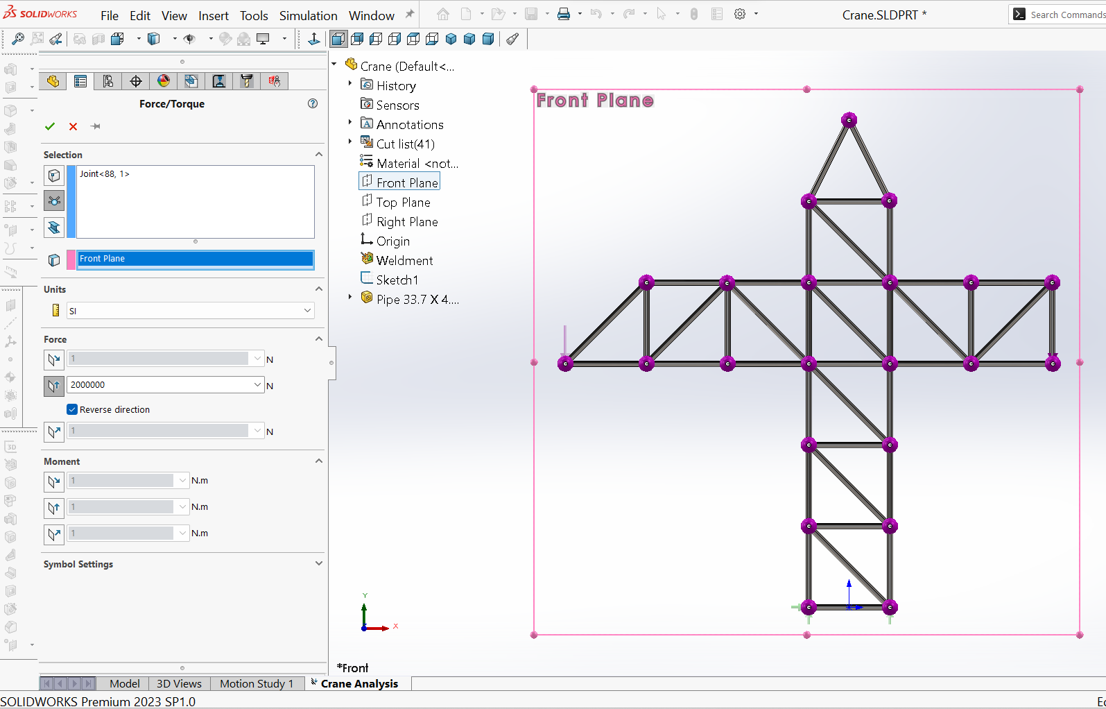
Different types of loads can be used in SOLIDWORKS Simulation. In this case, payload weights are required, represented by two vertical forces at joints $R$ and $W$. The loads are applied by using (right-click) the External Loads command under the simulation study tree and choosing Force. Then, from the Force PropertyManager that appears, under Selection, clicking on the Joints symbol followed by picking the joint (here: $R$ and then “W”) in the graphic window and selecting the options for the joint “R”, as shown in Figure 10, where a force of $1500 \ kN$ is applied, and for the joint “W”, Figure 11, where a force of $2000 \ kN$ is applied.
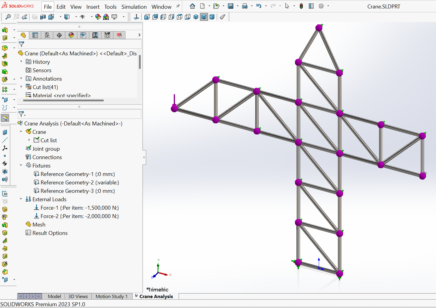
After completing applying the forces, the appearance of the model in the graphics window will be as shown in Figure 12.
$\quad$ 6. Meshing
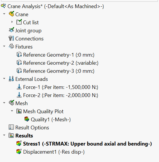
The mesh is created by using the command Mesh and Run, which combines the meshing and running of the analysis in a single step. After completing the meshing, the study tree will appear as shown in Figure 13.
Part D – Scrutinizing the results
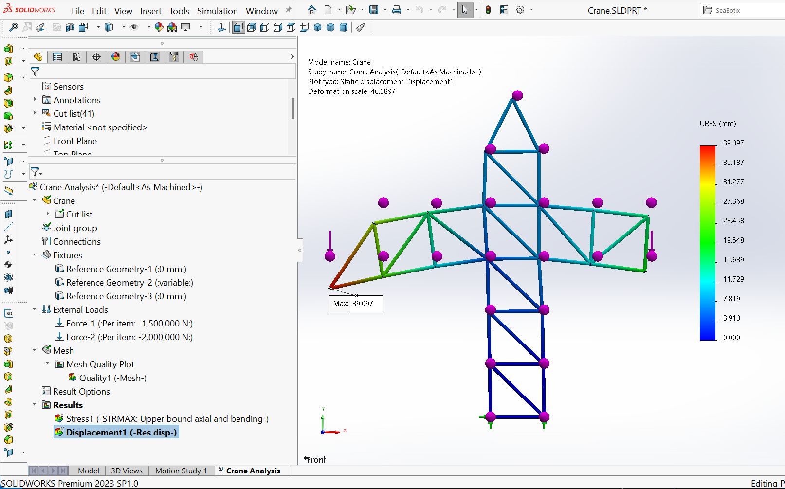
When SOLIDWORKS is used for static studies, it generally computes, among others, the Displacements (Figure 14) at the joints or nodes of the structure, the Factor of safety (Figure 15), the Reaction forces at the points of supports, the Strains/Stresses on an element/at the nodes, and so on.
The maximum resultant deformation
Figure 14 indicates that with a combined load of $3500 \ kN$ applied to the crane, the maximum deformation experienced by the joint $R$ is $39.097 \ mm$. Since a truss element has three translational displacement degrees of freedom at its node, the resultant displacement refers to the vectorial resultant displacement.
The factor of safety
The calculation of the factor of safety is based on certain failure criteria. SOLIDWORKS Simulation offers four failure criteria:
- Maximum von Mises Stress Criterion
- Maximum Shear Stress Criterion
- Mohr-Coulomb Stress Criterion
- Maximum Normal Stress Criterion (for composite shells)
Large factors of safety in a region indicate that material could be saved from that region. Many codes require a minimum factor of safety between $1.5$ and $3$.
- A factor of safety less than $1$ at a location indicates that the material at that location has failed.
- A factor of safety of $1$ at a location indicates that the material at that location has just started to fail.
- A factor of safety larger than $1$ at a location indicates that the material at that location is safe.
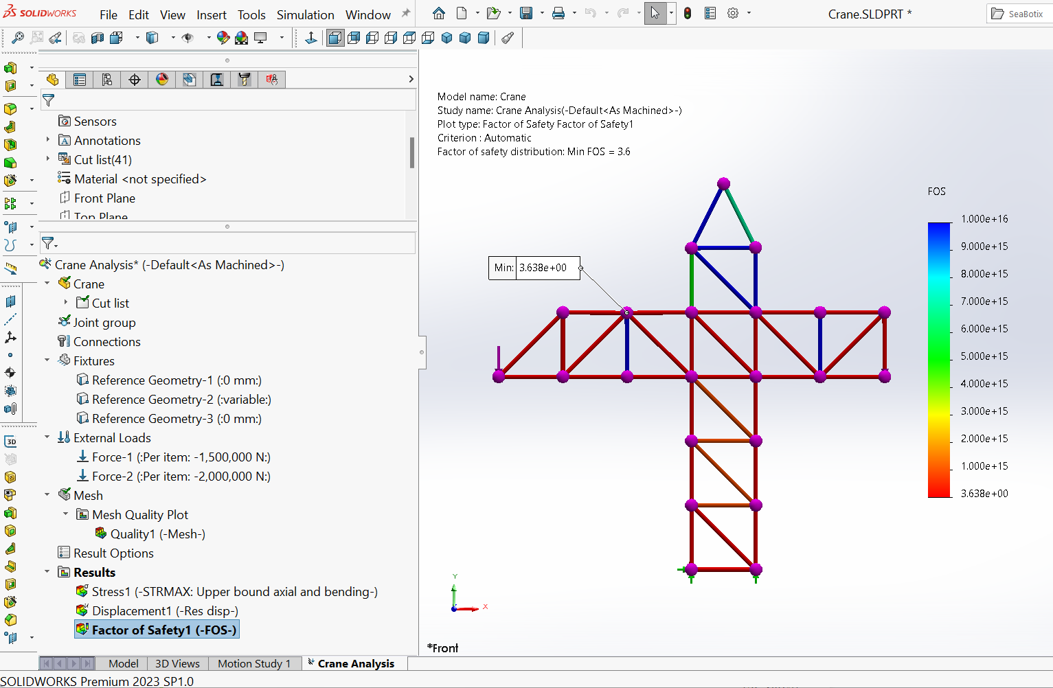
Figure 15 shows the distribution of the FOS for the crane upon the application of the load. Here, the Maximum Von-Mises failure criterion, specified in the material property database, is used.
The axial force/stress for the member $IH$
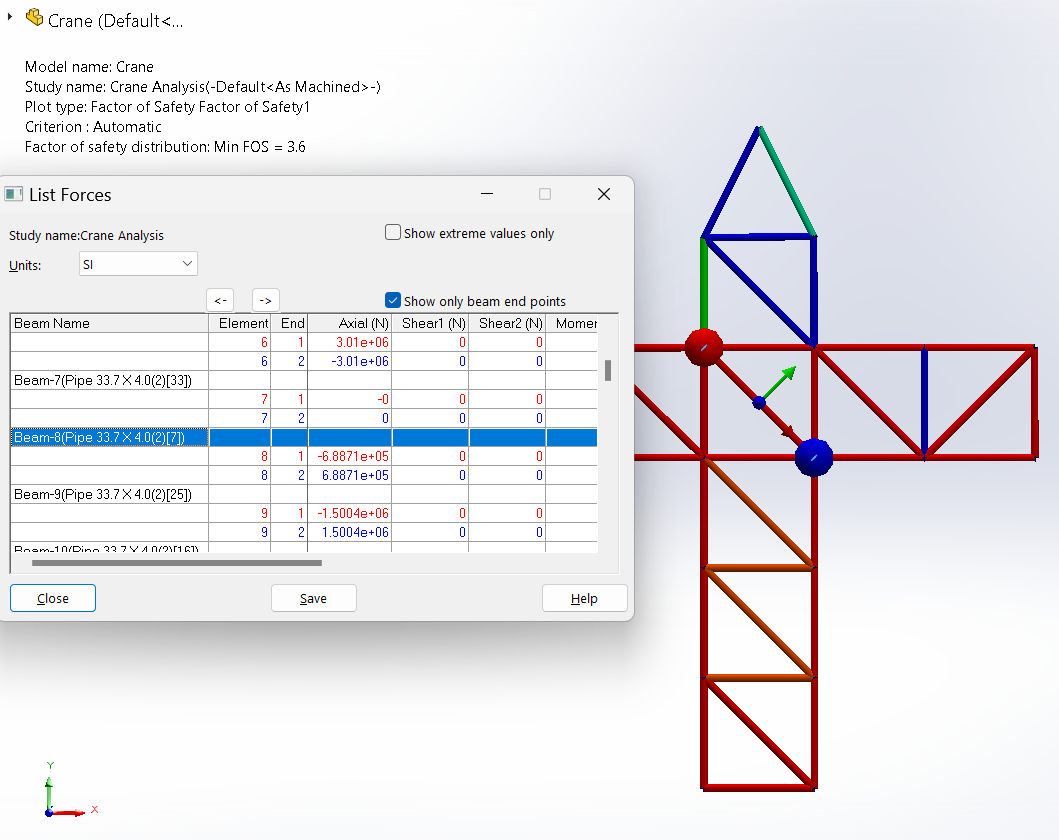
The List Forces window allows to navigate through the values of the axial forces developed in different members of the structure. For example, $Beam-8$ is the element that corresponds to member $IH$, which experiences an internal axial force of approximately $688.7 \ kN$ (Figure 16).
This value is approximately $3\%$ less than the value of the manual calculation $(707 \ kN)$ (tension) obtained in the following steps:
Taking a section through $KI$, $IJ$, $JH$ and $HT$, as shown in Figure 17(a).
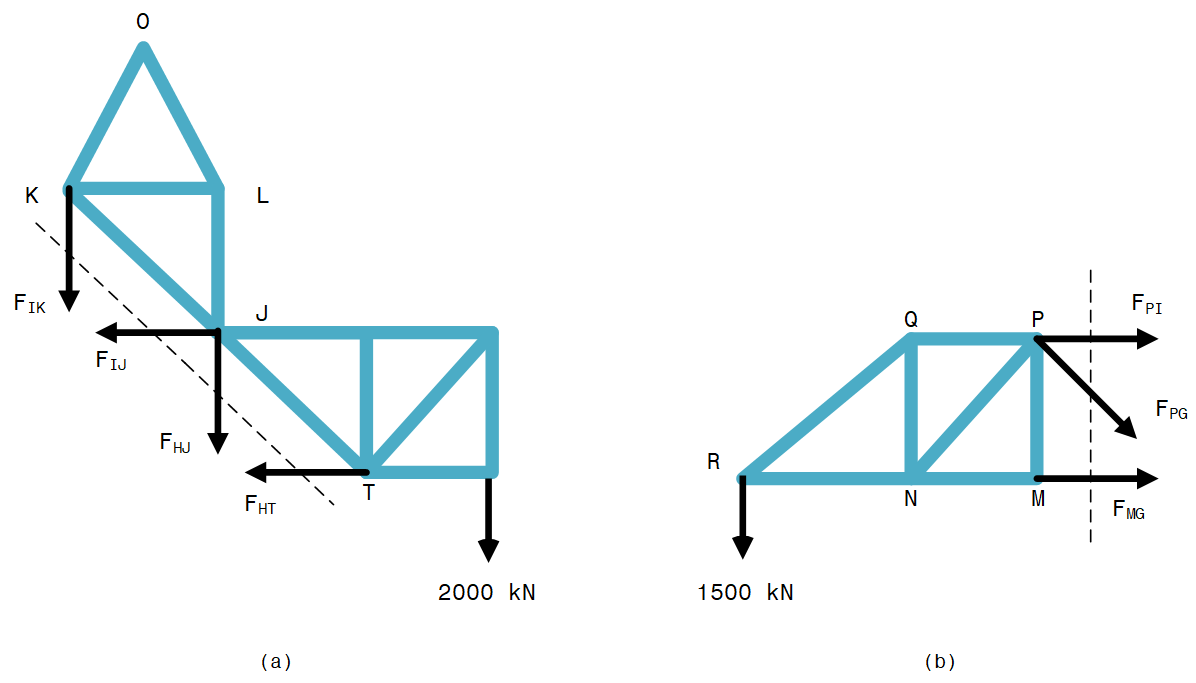
Taking moments about $J$:
\[F_{HT} \times 3 + 2000 \times 6 = 0 \\ \Rightarrow F_{HT} = -4000 \ kN\]Resolving horizontally:
\[F_{IJ} + F_{HT} = 0 \\ \Rightarrow F_{IJ} = +4000 \ kN\]By taking a section through $PI$, $PG$ and $MG$ as shown in Figure 17(b), and taking moments about $G$:
\[F_{PI} \times 3 - 1500 \times 9 = 0 \\ \Rightarrow F_{PI} = +4500 \ kN\]Resolving horizontally at $I$ in the complete truss:
\[F_{IH} \times cos45° + F_{IJ} - F_{IP} = 0 \\ \Rightarrow F_{IH} = +707 \ kN\]The small difference between the value from SOLIDWORKS and the manual calculation may be attributed to possible rounding-off errors.
PROBLEM 2: Conducting static analysis on loaded two straight connected segments of a machine
Problem Description
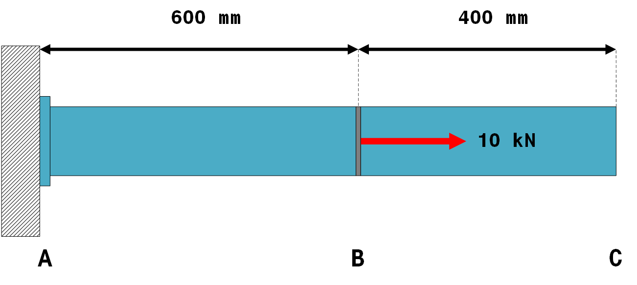
Figure 18 shows two straight segments of a machine loaded as illustrated. The segments are made of alloy steel and have a cross-sectional profile with an external and internal diameter of $40 \ mm$ and $20 \ mm$, respectively. The segments are treated as two connected bars.
Objectives
Using SOLIDWORKS Simulation to:
- Determine the displacement of the end $C$.
- Evaluate the axial stresses developed in the components upon loading.
Solution
- Part A – Creating the bar's skeletal model
- Part B – Converting the skeletal model into a structural profile
- Part C – Creating the Simulation study
- Part D – Scrutinizing the results
PART A- Creating the bar’s skeletal model
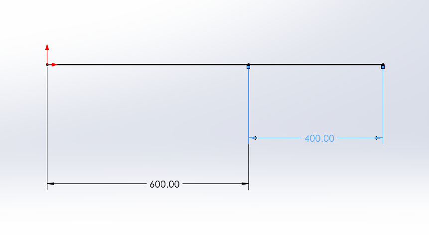
Part B – Converting the skeletal model into a structural profile
Figure 20 shows the structural model after adding structural properties to the skeletal model and editing the cross-section.
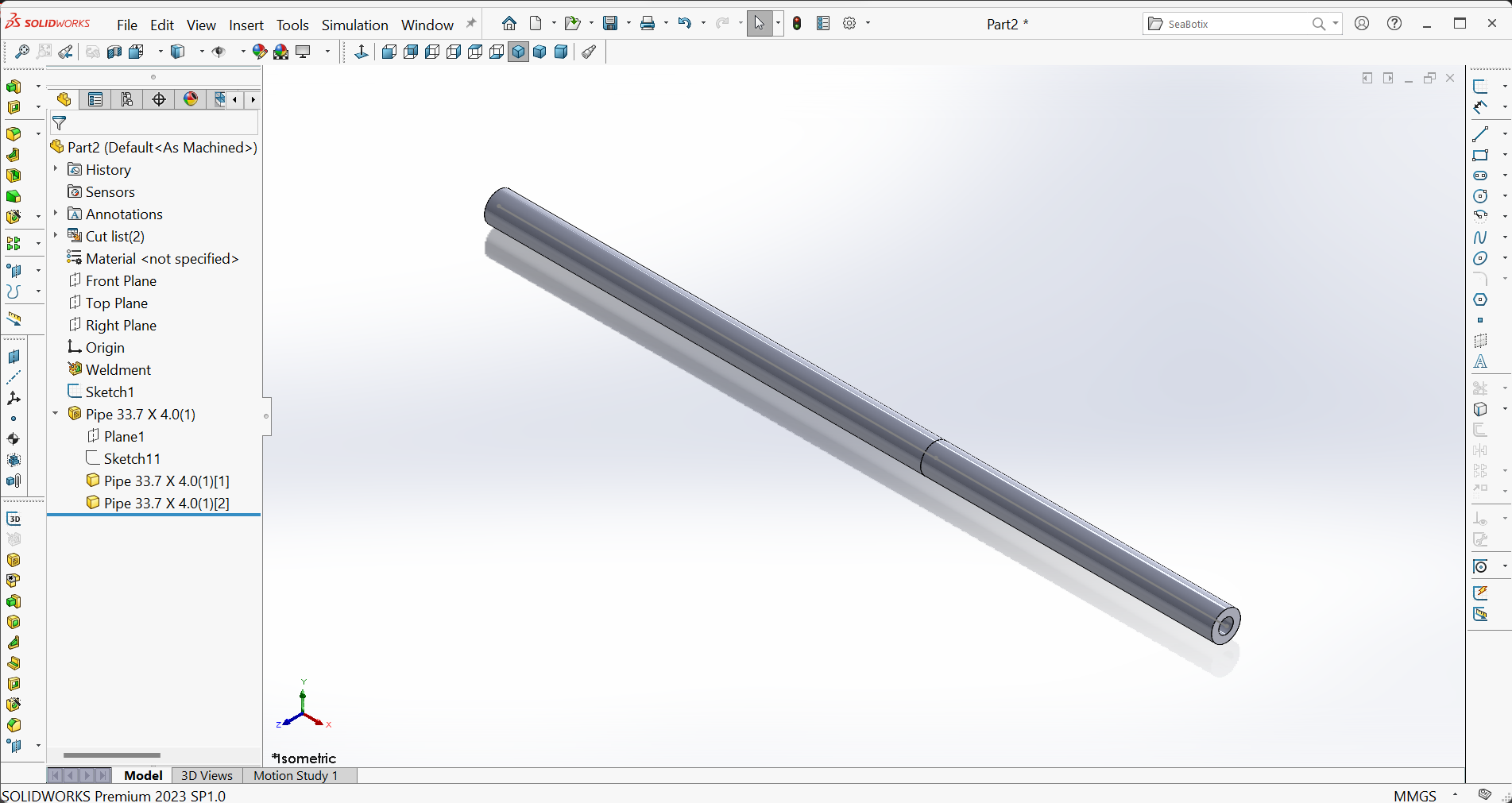
Part C – Creating the Simulation study
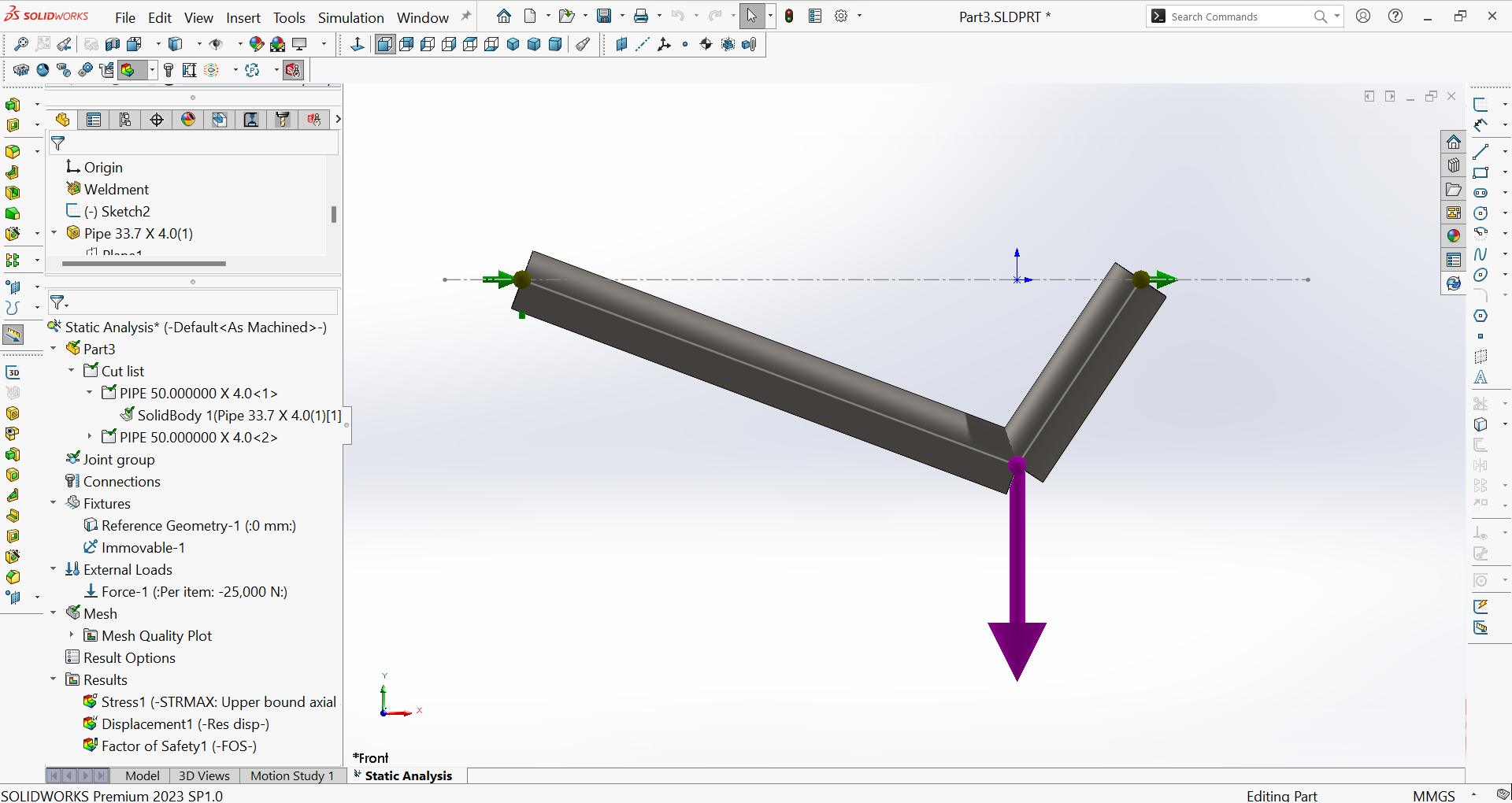
Figure 21 shows the result of creating a new study, specifying the material for the members (Alloy Steel), changing from a beam element to a truss element, applying fixtures (fixed support at joint $A$) and the load, and initiating the meshing process.
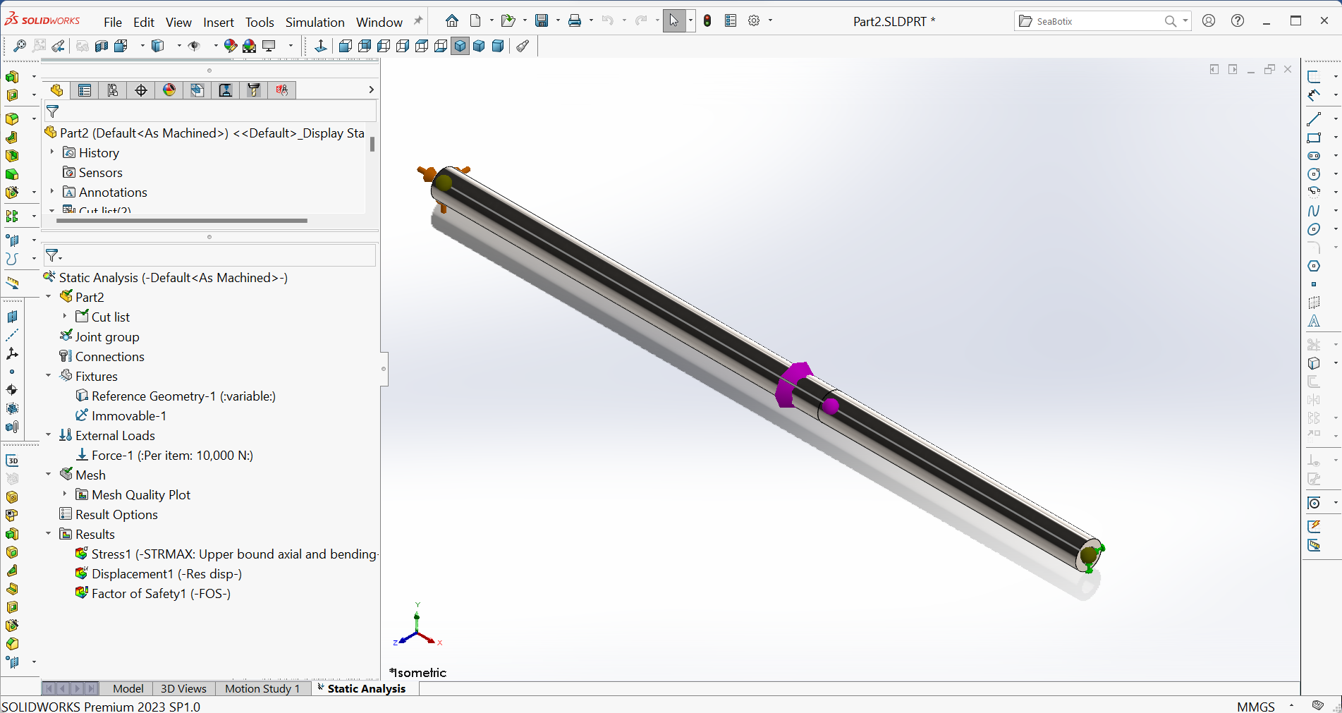
Part D – Scrutinizing the results
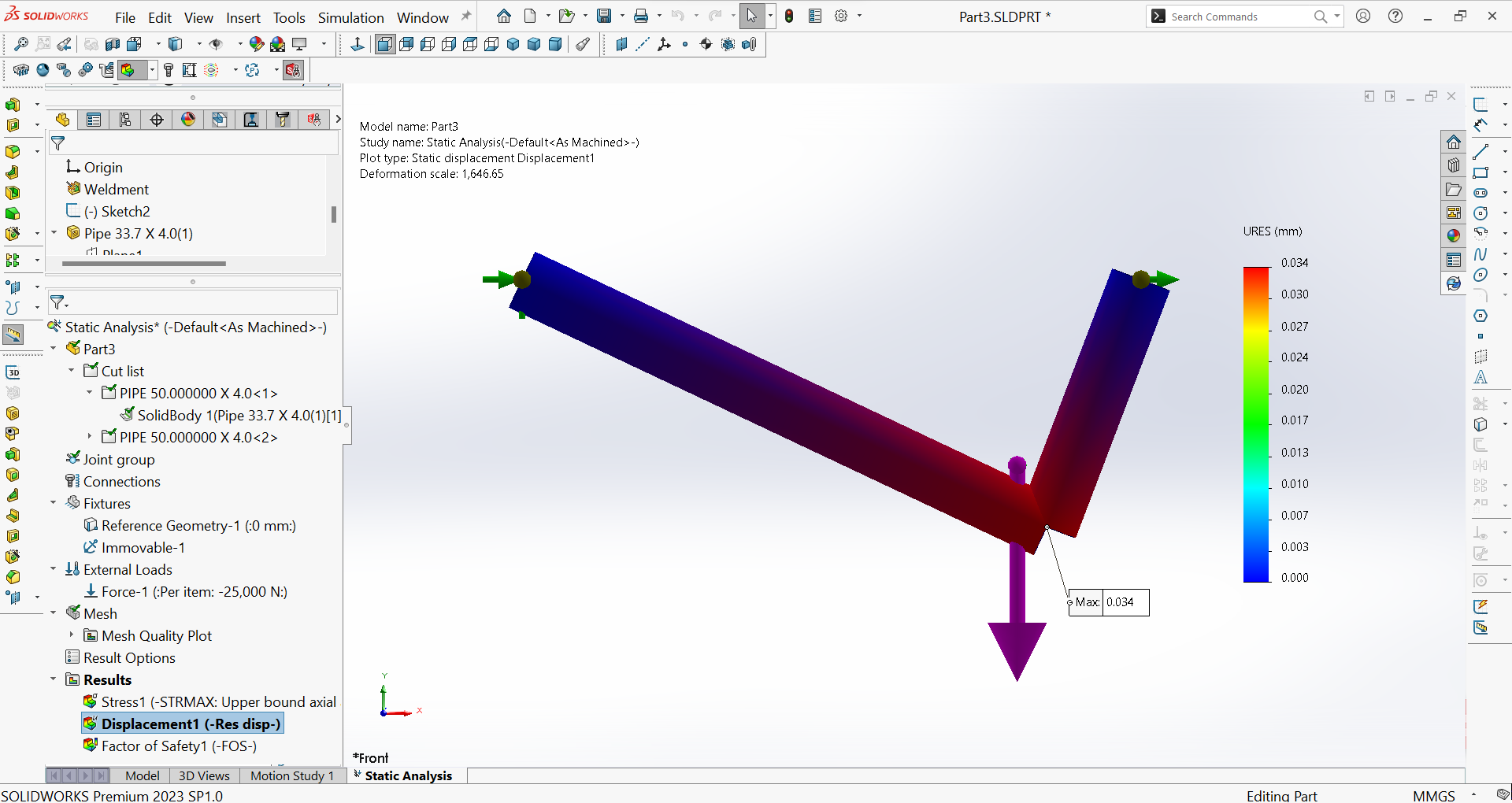
- Maximum displacement of end $C$: Figure 22 shows the displacement plot and the maximum resultant displacement, which occurs at the joint $B$ $(30 \ \mu m)$ and it equals to the displacement at the end $C$.
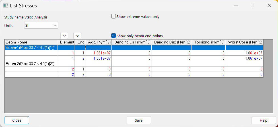
- Retrieving the axial stresses: Figure 23 shows the default display of axial stresses.
PROBLEM 3: Conducting static analysis on a load-supporting mechanism
Problem Description
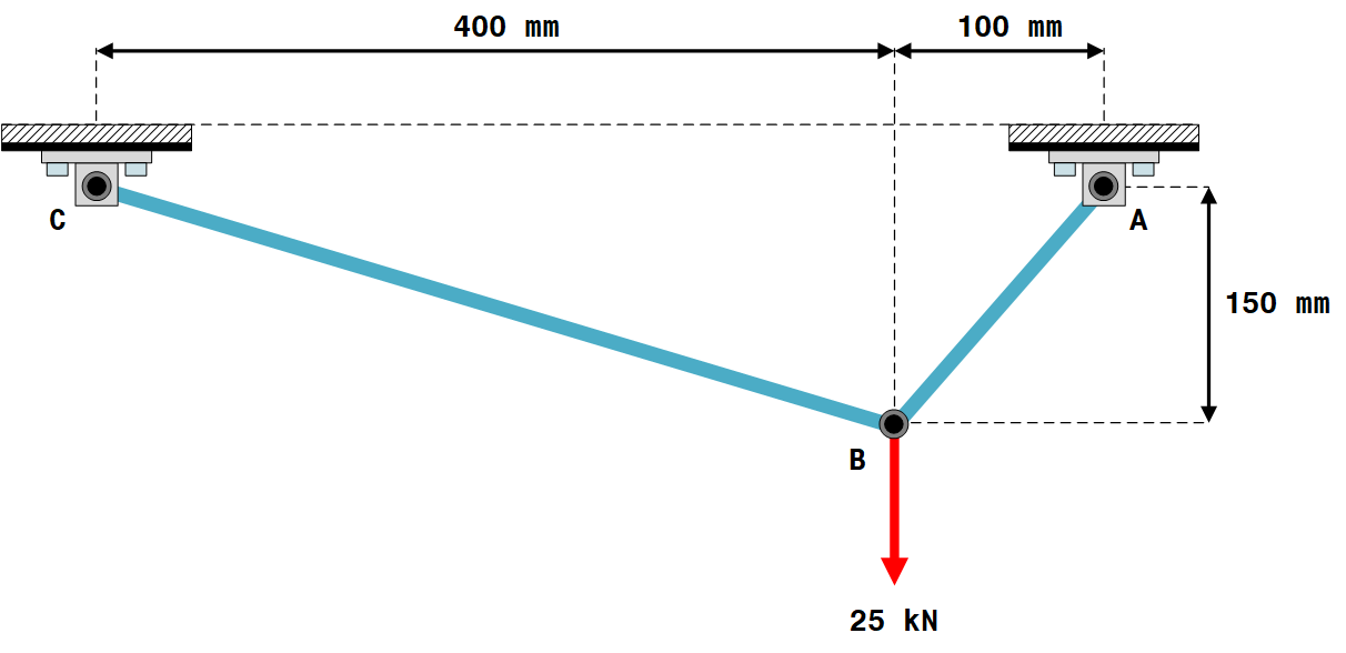
Figure 24 shows a 2D plane truss representing a load-supporting mechanism. Components $CB$ and $AB$ are made of $ASTM \ A-36$ steel tubes with the same crosssection (external and internal diameters of $50 \ mm$ and $30 \ mm$, respectively).
Objectives
Using SOLIDWORKS Simulation to :
- Determine the resultant displacement of joint $B$
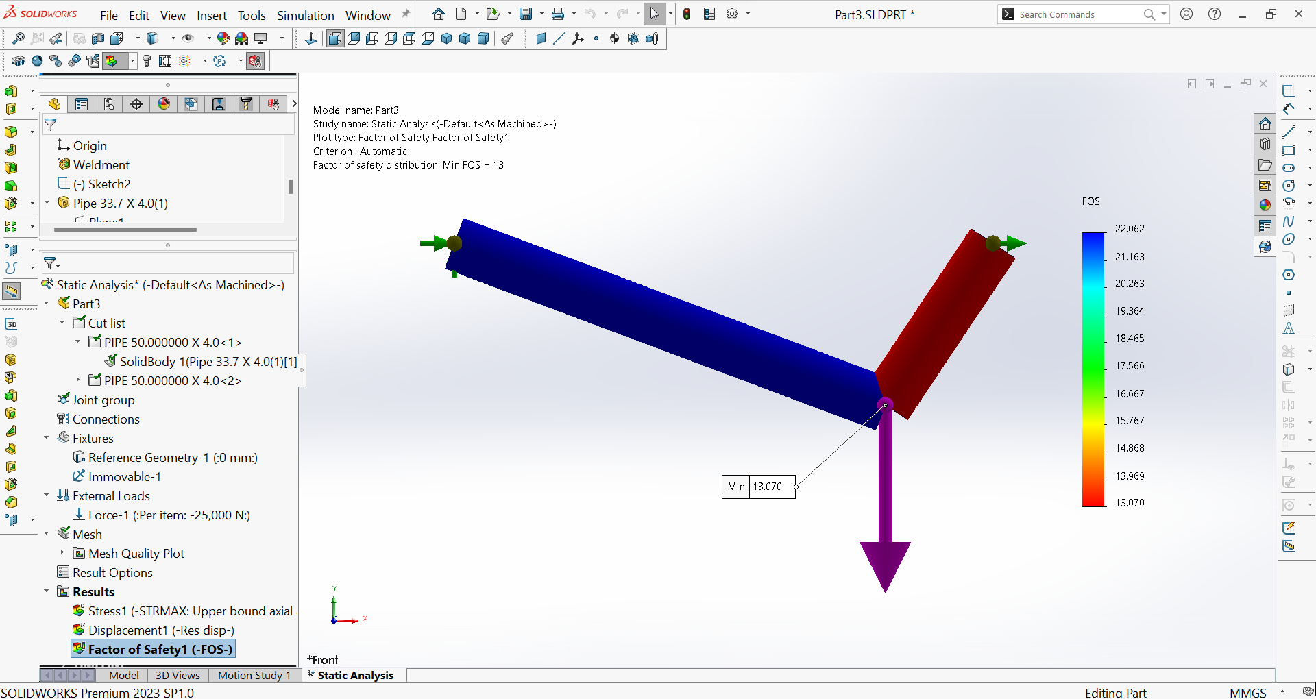
- Determine the minimum factor of safety of the assembly
Solution
- Part A – Creating the load-supporting mechanism's skeletal model
- Part B – Converting the skeletal model into a structural profile
- Part C – Creating the Simulation study
- Part D – Scrutinizing the results
PART A- Creating the load-supporting mechanism’s skeletal model
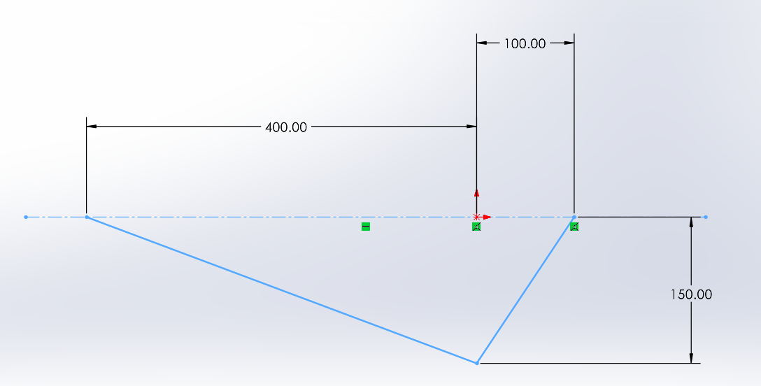
Part B – Converting the skeletal model into a structural profile
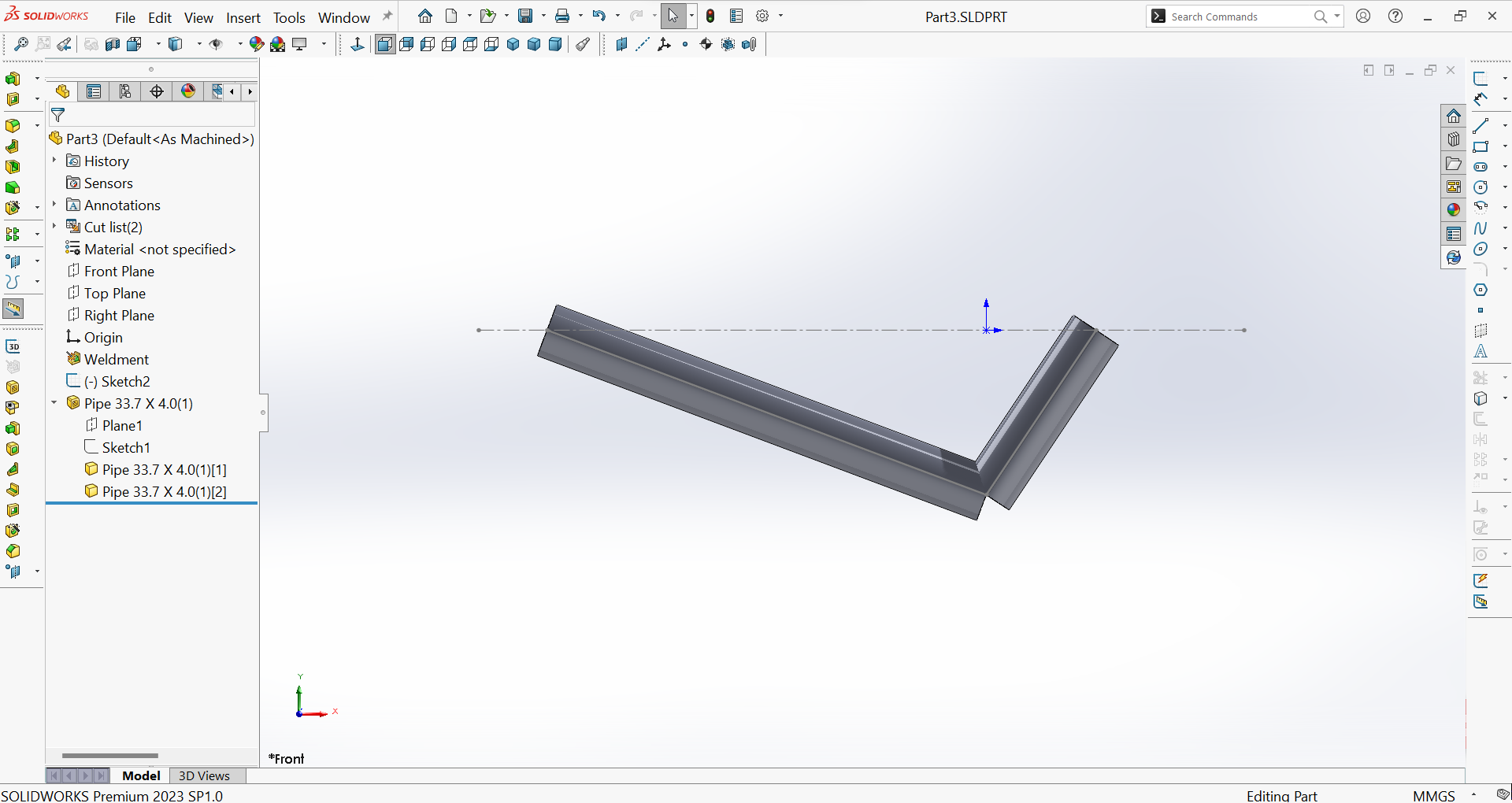
Figure 26 shows the structural model after adding structural properties to the skeletal model and editing the cross-section.
Part C – Creating the Simulation study
Figure 27 shows the result of creating a new study, specifying the material for the members $(ASTM \ A-36 Steel)$, changing from a beam element to a truss element, applying fixtures (fixed supports at joints $A$ and $C$) and the load, and initiating the meshing process.
Part D – Scrutinizing the results
- Resultant displacement of joint $B$: Figure 28 shows the displacement plot and the maximum resultant displacement, which occurs at the joint $B$ $(34 \ \mu m)$.
- Minimum factor of safety of the assembly: Figure 29 shows the minimum factor of safety of the assembly $(Min FOS = 13.07)$, indicating that the chosen material of the components is safe.